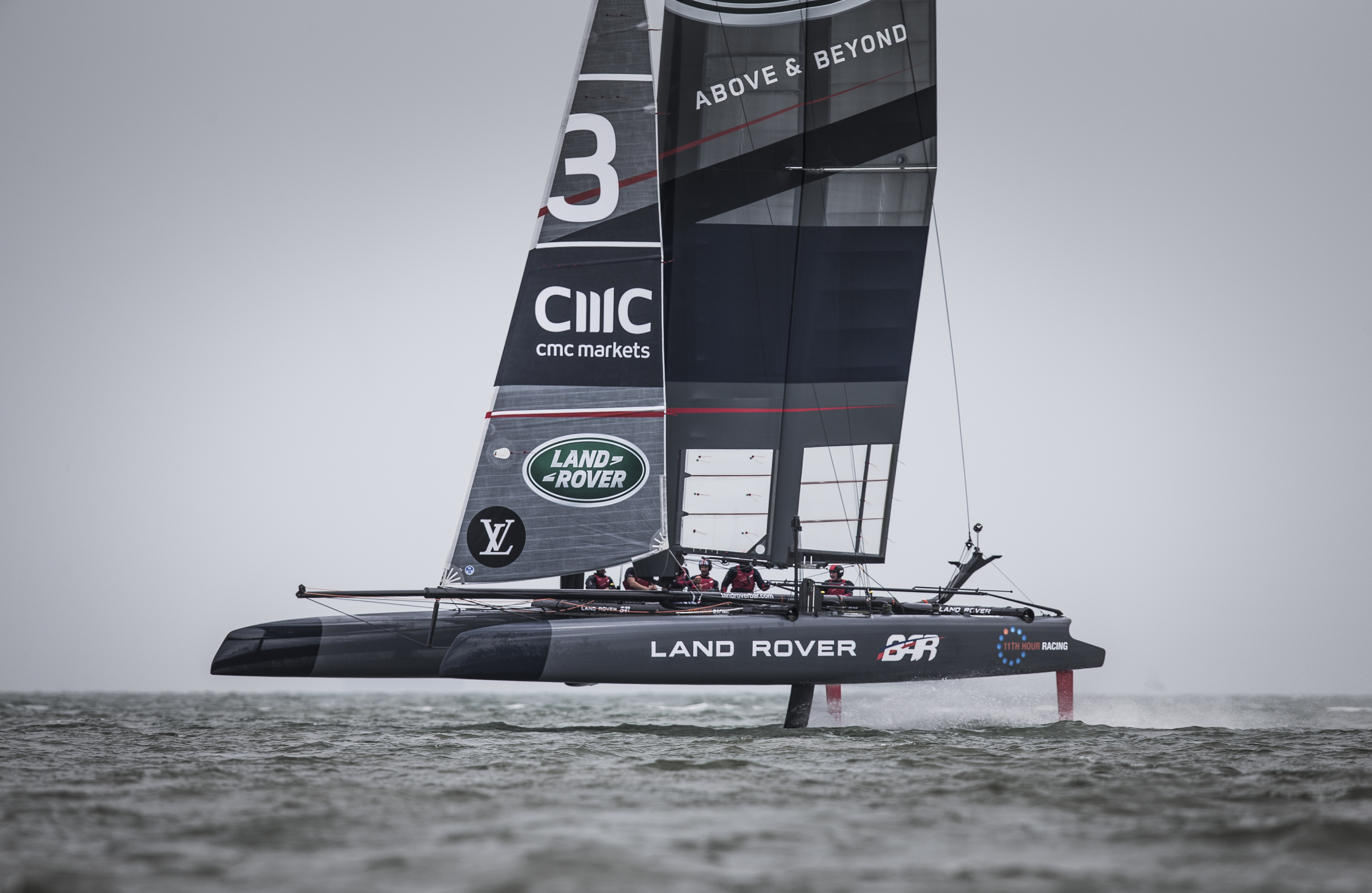
British Challenger in the 35th America’s Cup
The America’s Cup is considered the pinnacle of yacht racing. Countries compete for the oldest trophy in international sport in yachts that represent the cutting edge of yacht design and technology. The America’s Cup match is held between only two teams, the defender and one challenger. Cape Horn Engineering was proud to be at the core of the design team of Land Rover BAR, the British Challenger in the 35th America’s Cup. The ultimate goal is to #BringTheCupHome, where it all started in 1851.
Cape Horn Engineering was responsible for providing CFD analysis to the design team and was involved in the overall concept design of the boat and the performance prediction.
CFD analysis was required for multiple aspects of the design of the solid winged foiling catamaran and the CFD team spent a substantial amount of their time producing comprehensive aerodynamic and hydrodynamic models to feed the velocity prediction programs or VPPs and on the man-in-the-loop simulator. Thousands of simulations were required each time. In order to do this, all processes had to be streamlined with extremely efficient workflows and simulation setups.
One key benefit about working for America’s Cup teams is having access to large resources, in terms of thousands of licenses and computer cores. Our main tools were Simcenter STAR-CCM+ for the simulations and NX for CAD, but across other departments, we also used additional Siemens products, such as Teamcenter, HEEDS, and Fibersim.
In addition to the systematic aero and hydro simulations, quite a lot of time was spent on special investigations, such as Fluid Structure Interaction of daggerboards and rudders, the dynamics of dropping the daggerboard into the water, optimising the 2D foil sections of daggerboards and rudders, the dynamics of the catamaran taking-off or coming up onto the foils, complex flow phenomena such as cavitation and laminar to turbulent flow transition in 2D and 3D, and more.
Finally, we also made extensive use of two other types of simulations which contributed to most of our design decisions. These were rudder in the wake of the daggerboard simulations and simulations for the aero package. Both types of simulations are explained in more detail.
Rudder in Wake of Daggerboard
The simulations with the rudder in the wake of the daggerboard were free-surface simulations of the catamaran foiling on one daggerboard and the two rudders. The leeward rudders inevitably is in the wake of the daggerbord in front and is much influenced by its wake. In these simulations, which were run for different boat speeds, 4 degrees-of-freedom were allowed, and these 4 motions were adjusting during the simulation until they balance 4 target forces or moments coming from the VPP. The target side force from the wing or sail plan was balanced by the yacht drift or leeway. The yacht vertical force, mainly the yacht displacement, was balanced by the rake of the board. Target pitch and yaw moments from the VPP were balanced by the rudder base rake and rudder angle respectively.
For the output, we processed a myriad of information. The total drag and righting moments of the whole system were the main results we needed to achieve our objectives.
Data was also processed for the individual forces and moments on the board, leeward and windward rudders, blades and elevators, leeway of the yacht, board rake, rudder base rake, rudder angle, rudder shaft torques, bending moments on blades and elevators, areas prone to cavitation ( for instance on the board elbow or rudder to blade junctions ) and many more details of the flow such as the flow angles in planes in front of the rudders.
The main outputs were the total drag and heeling/righting moments. These were combined with derivatives coming from the VPP to obtain the VMG gains and losses. The VMG is the velocity made good or combination of boat speed and course angle relative to the wind. The end result of these simulations were a direct measure of the ability of the yacht to complete the race in the quickest manner, comparing different board candidates.
The derivatives from the VPP are sort of multipliers that give the trade-offs between differences in drag or righting moment, with a delta in boat speed. For instance, if the boat has 1 Newton less drag it could travel 0.001 knot faster, or if the yacht has 1 Newton metre more righting moment it could travel 0.002 knot faster and so on.
This was the main tool we used during our AC35 campaign to design the racing daggerboards and rudders. We considered the geometrical size and shape of daggerboards, rudder blades and elevators. We studied the influence of the structures, since the board shapes used in the simulations were already pre-deformed for the loading they were supporting. We looked at ways of sailing the boat, for example with respect to flight height, trim down by the nose, toe-in or toe-out for the rudders, optimal daggerboard cant angle for each speed, etc.
Platform Aerodynamics
The aero package included everything that was allowed by the AC rule to be modified above water. We ran simulations for probably a thousand different configurations, at two typical sailing conditions, one upwind and one downwind. We also used derivatives from the VPP in the same way as explained for the daggerboard-rudder investigations, to come up with the best VMG around the course. From comparing the configurations, 9 different configurations are shown below.
Moreover, we assessed all contributions to drag and righting moment, for each different part of the aero package, such as for each of the two hulls, for the forward and rear beams, the crew, etc as well as the contributions to driving force of the jib and wing, and their interaction with the platform.
Different wing and jib end-plates, below are some examples of the forward beam with different size, angle of attack and twist distributions. We also investigated the central pod shape, the crew in the standing or kneeling position, all sort of fairings, and a myriad of other details.
In some simulations we even included the trampoline, which is made out of kilometres of thin rope, meshing it, or otherwise considering it as a porous region. In some one-off simulations we also solved the flow around the standing and running rigging. Otherwise, as a default, the trampoline and rigging were taken into account as a post-processing step using coefficients and flow probes along the cables.
The Team Helping Land Rover Bar to #BringTheCupHome
Deborah Eppel, Technical Marketing Engineer at CD-adapco, talks with Cape Horn Engineering about the role simulation software has played in
the very competitive field of yacht racing, and how it has helped them discover better designs. Faster.
Please click the link to read the interview by CDadapco-dynamics-40. #BringThe CupHome