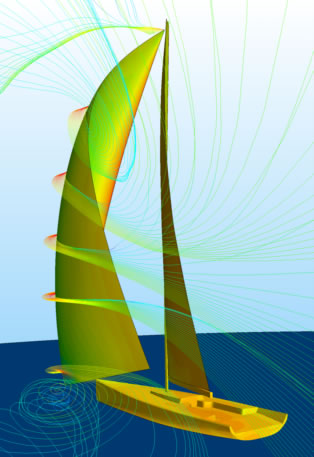
 In aerodynamic simulations we model all geometry above the static water plane, including the sails, mast, boom, deck and hull. The rig is tilted to the correct attitude accurately modeling heel, pitch and yaw. A varying wind profile is used to account for the boundary layer along the surface of the water. The aerodynamic computational models use automatically generated polyhedral meshes with prism layers.
All of our simulations are processed in parallel on many cores; with access to a large in-house cluster we can run over 100 cases concurrently. Each case is part of a matrix of predefined sailing conditions. In general hydrodynamic cases are run as unsteady simulations to allow free surface waves to develop. These take between 12 and 24 hours to complete. Alternately, most of our aerodynamic cases can be run as steady state simulations which converge quickly because there is very little separation on the sails of high performance racing boats. These sail cases generally run in only a few hours. Combined, this means we are capable of running several hundred simulations per day.
Similar to the wind tunnel, the major task in generating realistic sail coefficients is getting a good sail-trim over a range of apparent wind angles (AWA) and heeling moment (for depowering the rig). The process starts either with a database of sail trims to test provided by the sail designer, or with a parent sail shape. From the parent sail shape we create many variants using either a parametric morphing approach or an optimization algorithm that trims and deforms the parent in a range of conditions.


For sail analysis we use parametric modeling and Fluid Structure Interaction (FSI) codes. In parametric models we use CFD to find the optimal aerodynamic sail shape. Designers then develop a sail with the appropriate structural elements in order to achieve this optimal ‘flying’ shape. Parametric variation is done either by using a predefined matrix of variations, or by incorporating an optimizing algorithm in an iterative loop. We use modeFrontier to optimize flying shapes. Typical results see improvements in the order of 3% of the performance of sail sets. The optimization also gives a great insight into the depowering capabilities of the sail set. In FSI models, the CFD code passes pressure forces into a finite element model which then calculates the deformed shape of the sail. The new deformed shape is trimmed by the sail designer and put back into the CFD simulation. This cycle is repeated four to five times until convergence is reached.