Smart Green Shipping in the UK
Cape Horn Engineering were proudly commissioned by Humphreys Yacht Design to help validate and refine the performance of their patented FastRig solid wings, developed for Smart Green Shipping in the UK.
FastRig is an innovative, retractable, rigid wing sail, designed to be easily retrofitted to existing commercial vessels with available deck space. The FastRig provides propulsive thrust from wind, with the purpose of reducing fuel consumption, GHG emissions and operating costs on commercial vessels. It is designed and manufactured in the UK from 100% recyclable materials, to be easily retrofitted to existing commercial vessels with available deck space – bulkers and tankers. Some 40,000 of these ships are suitable for conversion to sailing hybrid.
Smart Green Shipping, which develops solutions to reduce emissions from the global shipping industry, has launched a £5 million research and development project. The collaborative three-year programme comprises a £3.2 million investment from the private sector and a further £1.8 million grant from Scottish Enterprise.

In this initial investigation, Cape Horn Engineering applied their 6-degrees-of-freedom simulation workflow to validate existing efficiency predictions obtained with a Velocity Prediction Program, which is based on individual force models. In contrast to the VPP predictions, the high-fidelity RANS-based CFD all-in-one simulations can capture all of the physics, including interactions between each wing and between the wings and the hull, all at once. This workflow has been recently developed by Cape Horn Engineering to directly compare the efficiency of wind assisted propulsion (WASP) devices and to validate lower fidelity modelling tools. For the case study presented here, power savings larger than 50% are demonstrated in moderate wind conditions of 20 knots from the side.

The Digital Twin
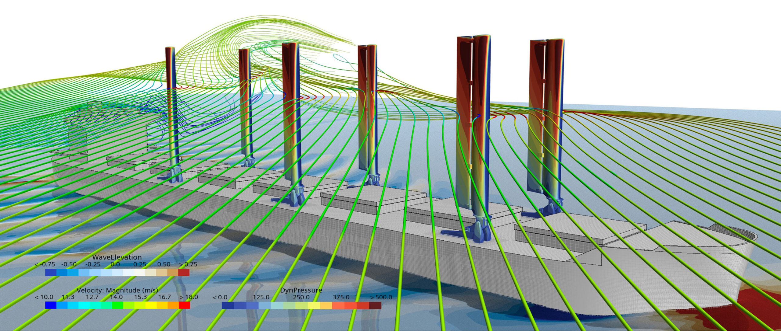
The high fidelity simulations take into account the most important effects of adding wings or any other type of wind powered device to a vessel. Both the water flow experienced by the hull at a given vessel speed and the air flow experienced by the 6 FastRigs are modelled simultaneously in a single simulation. The wings are mounted on deck, and aerodynamic details include the hull top sides, deck, hatches and superstructure. The wind speed and direction was varied to simulate different real world conditions, and the simulations were repeated with the vessel without the wings to have an exact baseline for comparison.
The wind conditions above the water surface are modelled with an accurate wind profile taking into account the atmospheric boundary layer wind gradient. This results in a variable apparent wind speed and direction at different heights, due to the combination of a moving ship and a wind strength that varies with height, something that sailors are very much aware of so that they need to twist the sails towards the top of the mast.
In the simulations, the vessel is sailing at a constant speed of 11.5 knots, and an actuator disk models the effect of the propeller using the open water propeller curves. Depending on the vessel resistance and the amount of thrust generated by the FastRigs, the thrust produced by the propeller balances the degree-of-freedom in the direction of travel and is used as an input to the actuator or virtual disc model. This determines the propeller RPM and propeller torque and therefore the delivered power.
The simulation further considers the deformation of the free surface or waves generated by the vessel, the dynamic sinkage and trim, the drift or leeway angle, the heel angle and the rudder angle to keep a constant course. The wind forces on the hull, superstructure and FastRigs induce the drift and heel angles, with the rudder angle changing during the simulation via a PID controller, balancing the yaw moment of the whole system. Thus, in total the 6 degrees-of-freedom are considered.
The simulation are stopped once they have converged to a quasi-steady solution. Then, comparing the case of the vessel with and without the FastRigs for the same wind conditions, the reduction in delivered power to the propeller can be compared, and with that the engine fuel and emissions reduction.
The table below shows the conditions investigated. At 11.5 knots, two True Wind Speeds of 12 and 20 knots each at 3 True Wind Angles of 70, 100 and 135 degrees were simulated. For each of the 6 combinations, the wings were adjusted with a different sheeting angle or rotation with respect to the vessel centre line. These values were taken as best estimates from existing VPP predictions, however, the sheeting angles of the 6 wings, independently of the position on deck, were the same within each simulation. The flap angle with respect to the chord line of each main wing element was also the same for all wings and all wind conditions. Greater performance could be achieved in the future from aerodynamic simulations to trim the 6 wing angles and 6 flap angles independently for a given wind condition.

Results
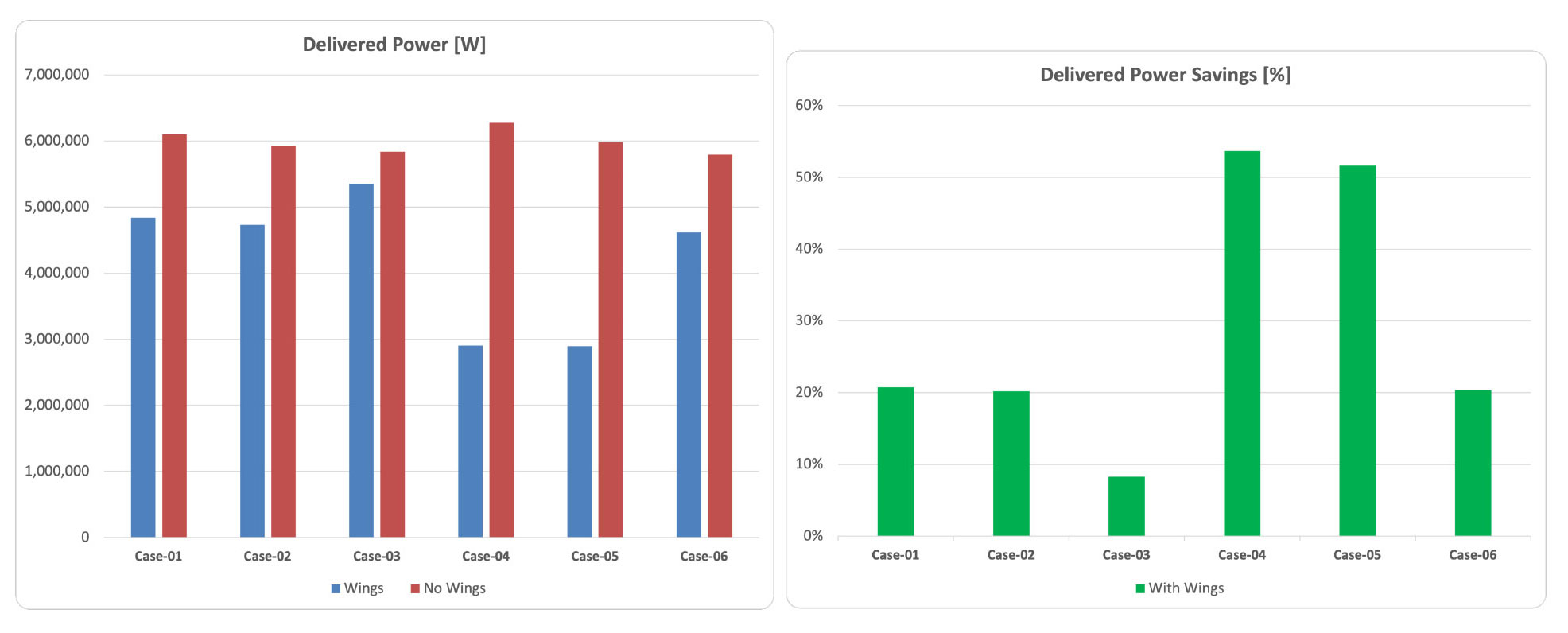
Figure 1 gives the delivered power results from the simulations, shown in watts on the left graph, and as power saving percentage on the right. For the 6 conditions investigated, the minimum savings are 8% and the maximum 54%, with an average saving of 29%. The maximum saving occurs for the stronger wind of 20 knots from the side, and the minimum for the lighter wind from the aft quarter, since the apparent wind speed is most reduced in this case. A 54% power reduction is a considerable amount, and this value could improve even further if a more adequate propeller is used for motor sailing conditions. Ideally, the vessel would be fitted with a controllable pitch propeller to always be operating at the optimum efficiency, thus have the greatest benefit from wind assisted propulsion. At higher wind speed the vessel could even be sailing with the engine just idling.
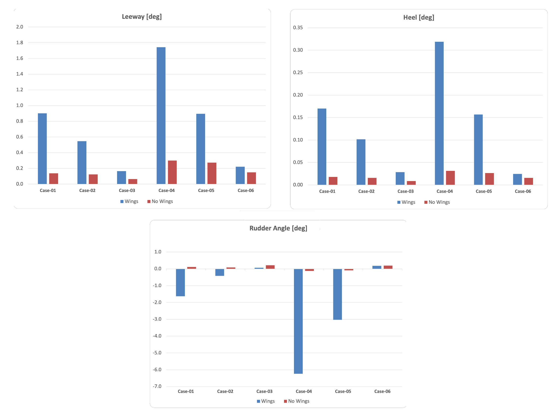
Another interesting aspect of the results is that the heel and leeway angles are very modest, see Figure 2. The rudder angles needed to maintain a constant course get larger for the stronger winds from the side. However, by trimming the wings differently forward to back, the yaw moment could be reduced and an optimum in efficiency found. This remains the objective of a follow up investigation.

Figure 1: Delivered Power and Power Savings

Figure 2: Leeway, Heel and Rudder Angles

